UDP, ICMP, IP 协议校验和的计算
UDP, ICMP, IP 协议校验和的计算
最近在实现一个简单的 udp 协议栈, 几乎每一层的协议都要计算校验和. 总结一下校验和计算的过程, 也希望对他人有用.
1. 校验范围
虽然每个协议里都有校验和字段, 但是每个校验和覆盖的范围都是不同的:IP 协议: 只包含 20 字节的 IP 报头
ICMP 协议: 整个 ICMP 报文 (ICMP 报头 + ICMP 数据)
UDP 协议 / TCP 协议: 除了整个 UDP/TCP 报文以外, 前面再加上一个 12 字节的伪 IP 报头. 对这个整体一起算校验和 (见下图)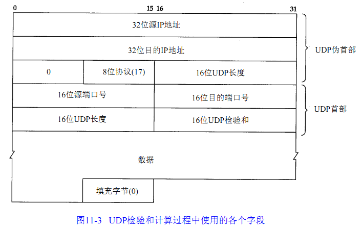
图 from:TCP/IP 详解
另外, 如果接收到的 UDP 校验和为 0, 则说明不要进行校验和计算
2. 计算步骤
发送时:将校验和字段置零
对校验范围逐 16bit 做反码和
得到的和即为校验和
接收时:
对校验范围逐 16bit 做反码和
若校验和为 0 则正确, 否则错误
3. 如何计算
反码: 这里的反码指的是对原来的数所有位二进制取反, 既: unsigned int A 的反码为~ A对每个数求反码然后相加, 如果最高位有进位则加到最低位 (循环进位)
如果是奇数个字节, 将最后一个字节 (设为 Z) 扩展成: [Z, 0x00]
由上面简单的解释, 我们可以写出一个最直观的算法, 本人自己写了一个, 感觉太烂了就不放出来了.
4. 优化
事实上, 我们一直没提到二进制反码和的优点, 在 RFC1071 中详细的提到了反码和具有的数学上的优点, 利用这些, 可以有效加快校验和的计算:在计算时先求反再相加和先相加再求反结果一致
延迟进位 (在 32 比特加法器中进行 16 比特求和,这样溢出就被放到了高 16 位中。这种方法可以避免使用进位敏感指令但需要两倍于在 32 比特寄存器相加的加法运算。速度提高取决于具体的硬件体系。)
字节顺序无关
第二点对于 32 位机很好, 但是在 8 位单片机上就有点…
然后, 在 RFC1071 中还给出了一个利用了这些优化的 C 示例:
1 | static unsigned short checksum(unsigned short* data, int size) |
作者使用一个 32 位的 sum 来保存计算结果. 11 行是处理奇数个数据的. 最后一个循环是把进位加到低位上.
看到这么好的实现, 我也放弃用我自己写的了, 干脆用这个. 另外, stm32 中有一个硬件实现的 CRC 模块. 下次移植到 stm32 上的时候用用它试试.
一个方便的 Image_slider 的 jQuery 代码
UDP, ICMP, IP 协议校验和的计算
1 | <html> |
自己造操作系统 (1) – 开篇, zOS
自己造操作系统系列 0.1 版
[最近一直都忙着造轮子, 博客都没空写. 今天算是把调度器写出来能用了, 算是取得阶段性成果, 过来记录一下.]
zOS: 是本人一星期前开始的项目, 目标是做一个 stm32 平台上的非实时操作系统.
features:
初期的想法是这样:
(“应用”, 或” 应用程序” 指的是在 zOS 操作系统上运行的用户态程序)
- 对于应用开发:
多进程
应用程序 (用户态程序) 可以独立编译, 无需和操作系统代码一起编译
烧入芯片前用一个叫做 zImage 的工具 (我把操作系统和 app 合成之后的镜像叫做 zImage) 把 app 的 binary 和操作系统的 binary 合成为一个二进制 Image 文件. 之后烧入到芯片 flash 中
上面功能使用 pic(位置无关代码) 实现
调度器使用抢占式时间片轮转算法 (暂时还没实现基于优先级的调度)
向用户态程序提供 svc 系统调用 (供汇编程序调用), 同时提供 libc 形式的系统调用 (供 c 语言调用, 相当于对裸的 svc 加了一层 wrapper)
libc 中另外还提供 c 标准库 (newlib)
对于有 MPU 的器件使用内存保护
这么设计的好处是开发应用程序时就好像开发 PC 系统上的程序一样了, 不需要把 OS 的代码放到项目中去. 看着清新了很多.
使用系统调用的方法使应用编写方便了很多, 而且还安全.
- 对于驱动开发:
提供自旋锁, 信号量等设施
暂时不提供子系统 (因为现在只面向 stm32 平台, stm32 标准外设库的头文件可以直接引用. 以后考虑移植到其他平台时再提供一个统一界面的子系统层)
…. 还没想好
3. 对于用户:
提供 shell(初步想法用 lua 实现, 不知可行性如何) [串口]
提供 GUI [液晶屏]
关于 build:
zOS 使用 CooCox 开发环境开发 (因为比较熟悉 GNU 工具链, 而且 CooCox 调试也方便).
现在只提供 CooCox 的项目文件, 以后会提供 Makefile. (关键我现在懒着写 -.-)
可以现在这里下载:https://lengzzz.com/zOS/zOS-0.1-alpha.tar.gz 写的还很烂 [掩面], 大神轻点喷 -.-
如果手上有 stm32 的板子的话可以编译了烧上去看效果. 现在就是一个简单的调度器, 开启了两个进程, 一个让 led 闪烁, 一个让 led 常亮. 时间片设置的大了一些 (为 1 秒). 所以运行会看到 led 一秒闪烁一秒常亮.
板子和我不一样的 (肯定不一样吧!) 需要把 Unit_Test/test_schedule.c 文件中关于 led 改成你的板子的 GPIO 端口. 这个估计难不倒大家.
后续会写文章一步一步记录开发过程…
在 keil 中使用 jlink
在 keil 中使用 jlink
先安装 jlink 的工具包. 在官网下载需要输序列号, 鉴于国内大多使用盗版. 在本站放一个镜像供大家下载: https://lengzzz.com/download/Setup_JLinkARM_V480.zip
下载后安装
安装好之后插上 jlink. 打开 keil
点击 Target Option 按钮: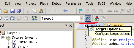
然后打开 Debug 选项卡, 选择右边的 use jlink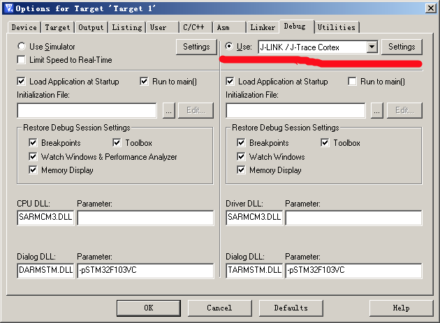
然后点击 Utilities 选项卡, 也选择 jlink: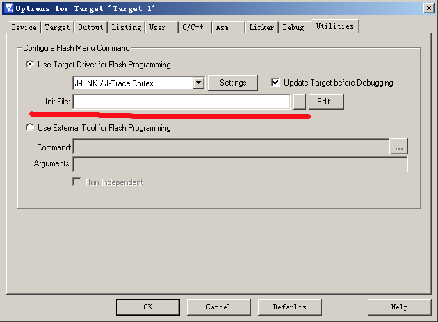
接着点击 Settings 选择 add 然后在列表中选择我们的器件: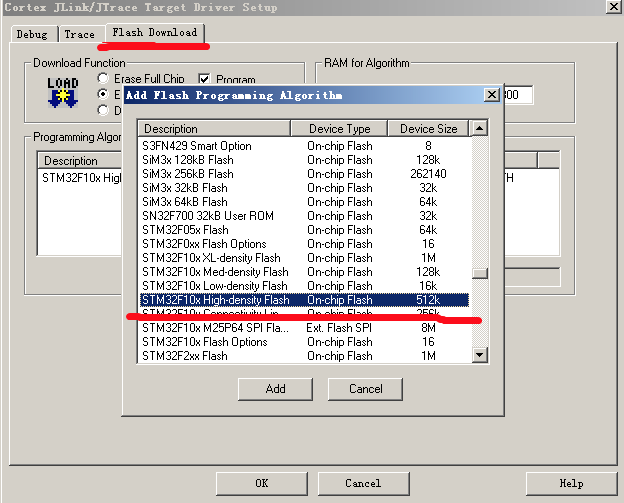
之后勾选上 Reset and run: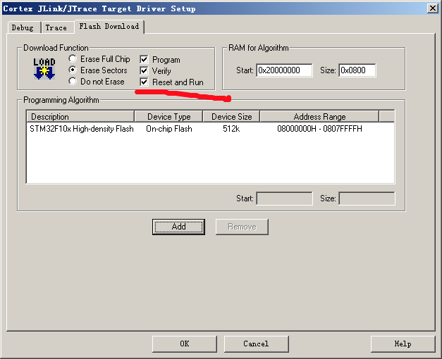
一路 ok 后, 应该可以下载和调试程序了
CodeVisionAVR C 编译器数据类型
CodeVisionAVR C 编译器数据类型
| 类型 |关键字 | 大小 (位) | 范围|
| | | : |:|
| 位型 | bit | 1 | 0, 1|
| 字符型 | char | 8 | -128, 127|
| 无符号字符型 | unsigned char | 8 | 0, 255|
| 有符号字符型 | signed char | 8 | -128, 127 |
| 整型 | int | 16 | -32767, 32768|
| 无符号整型 | unsigned int | 16 | 0, 65536|
| 短整型 | short int | 16 | -32767, 32768 |
| 无符号短整型 | unsigned short int | 16 | 0, 65536 |
| 长整形 | long int | 32 |-2147483648, 2147483647|
| 无符号长整形 | unsigned long int | 32 |0, 4294967295|
| 浮点型 | float | 32|
| 双精度浮点型 | double | 32|
avr 是小端模式
麻痹的! 傻逼 CodeVisionAVR 改什么语言, 把 const 和 flash 等价. 艹, 移植麻烦死
arm-linux 汇编 (4) – 函数调用规则
arm-linux 汇编 (4) – 函数调用规则
本篇主要考虑整数 (更精确点是 32 位整数) 作为参数和函数返回值时的传递规则.
网上很多资料都在说 arm 汇编中如果参数小于四个 (整数) 的话, 使用 r0, r1, r2, r3 来传递. 当大于 4 个时使用栈来传递. 但是究竟放到 sp 的上面还是下面, 顺序如何. 这次就来试一试到底是怎么样的.
1 | int a7(int a, int b, int c, int d, int e, int f, int g) |
编译以上代码 arm-linux-gnueabi-gcc -c arg.c 生成 arg.o 文件. 然后使用 arm-linux-gnueabi-objdump -d 来反编译. o 文件.
1 | 000001b4 <a7>: |
得到以上文件
下面来分析一下.
在 test 函数中. 我们先不管 fp 寄存器, 只看 sp 寄存器. sp 寄存器一上来就向下移了 16 个字节 (4 个 int). 我们知道, arm 的栈是 FD 的 (Full decrease, 既 sp 指向栈顶元素, 栈向低地址增长). 所以就是说明新开辟了 4 个 int 的空间.
然后 224 到 238 这段. 是将 5, 6, 7 这三个参数存到 sp 和 sp 上面. 使用了 3 个 int 的空间.
之后, 又将 1, 2, 3, 4 这四个参数分别保存到 r0, r1, r2, r3 中.
最后, bl 调用函数.
由上面分析可知, 当我们调用一个函数前, 应当:
前四个参数使用寄存器传递
后面的参数使用栈传递
使用栈传递时, 从后向前依次压入参数. 压栈完成后, sp 指向最后一个参数
sp 是 8 字节对齐的 [我猜想的]
刚刚的分析中, 我们只需要额外传递 3 个参数, 可是我们在栈上分配了 16 个字节, 另外我尝试传递 5 个参数时分配了 8 个字节 (也是多一个) 所以我猜想 sp 可能需要 8 字节对齐.
然后对于被调用的函数来说, 它知道的信息就是: “我的前四个参数在寄存器中, 我的 sp 指针指向最后一个参数, 依次向上可以得到全部参数.”
然后对于被调用函数来说, 它会将 fp 指向参数的后一个字. 让 sp 指向栈顶. fp 和 sp 之间保存断点信息 (保护上一函数的寄存器) 和自己的局部变量.
[EOF]
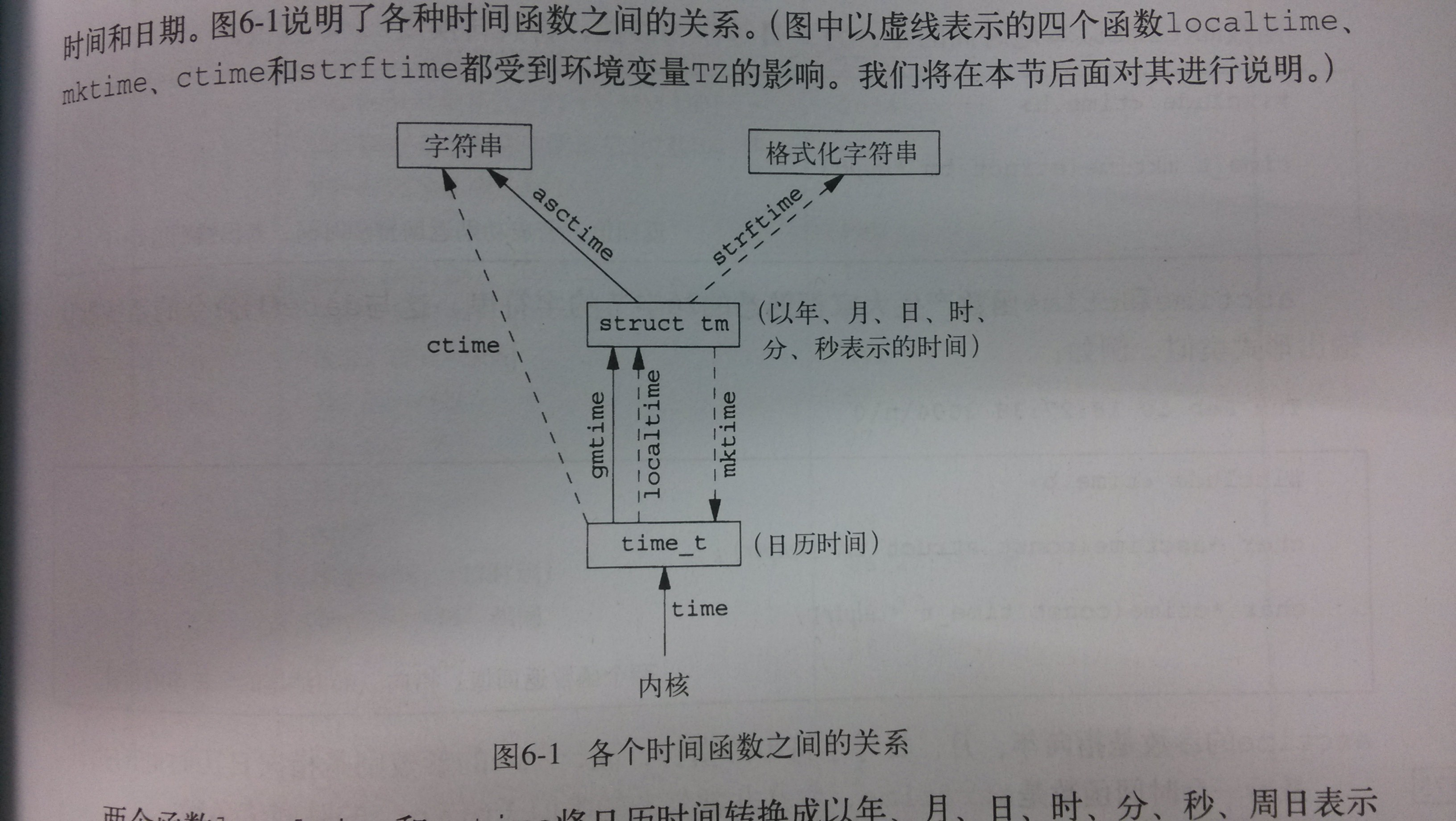
这张图把 unix 时间相关函数全部说明了
真是好不容易才找到 RK3066 的手册啊 赶快传服务器上备份
真是好不容易才找到 RK3066 的手册啊 赶快传服务器上备份
下载地址:https://lengzzz.com/download/Rockchip%20RK30xx%20TRM%20V2.0.pdf
网上搜到的 reference manual 都是十几页, 好不容易才从一个国外小网站找到这个 1000 + 页的. 估计是泄露出来的
ARM 核和 ARM 指令集大致是这样对应
ARM 核和 ARM 指令集大致是这样对应
ARM7TDMI ARMv4T
ARM9E ARMv5TE
ARM11 ARMV6
cortex ARMv7
下面是网上找的乱七八糟的列表 将就着看 反正 cortex 以前的都是老黄历了 唉
ARM7TDMI
v4T
ARM7TDMI-S
v4T
ARM7EJ-S
v5E
DSP,Jazelle
[译注 3]
ARM920T
v4T
MMU
ARM922T
v4T
MMU
ARM926EJ-S
v5E
MMU
DSP,Jazelle
ARM946E-S
v5E
MPU
DSP
ARM966E-S
v5E
DSP
ARM968E-S
v5E
DMA,DSP
ARM966HS
v5E
MPU(可选)
DSP
ARM1020E
v5E
MMU
DSP
ARM1022E
v5E
MMU
DSP
ARM1026EJ-S
v5E
MMU 或 MPU
[译注 2]
DSP, Jazelle
ARM1136J(F)-S
v6
MMU
DSP, Jazelle
ARM1176JZ(F)-S
v6
MMU+TrustZone
DSP, Jazelle
ARM11 MPCore
v6
MMU + 多处理器缓存支持
DSP
ARM1156T2(F)-S
v6
MPU
DSP
Cortex-M3
v7-M
MPU(可选)
NVIC
Cortex-R4
v7-R
MPU
DSP
Cortex-R4F
v7-R
MPU
DSP + 浮点运算
Cortex-A8
v7-A
MMU+TrustZone
DSP, Jazelle
[译注 2]:Jazelle 是 ARM 处理器的硬件 Java 加速器。
[译注 3]:MMU,存储器管理单元,用于实现虚拟内存和内存的分区保护,这是应用处理器与嵌入式处理器的分水岭。电脑和数码产品所使用的处理器几乎清一色地都带 MMU。但是 MMU 也引入了不确定性,这有时是嵌入式领域——尤其是实时系统不可接受的。然而对于安全关键(safety-critical)的嵌入式系统,还是不能没有内存的分区保护的。为解决矛盾,于是就有了 MPU。可以把 MPU 认为是 MMU 的功能子集,它只支持分区保护,不支持具有 “定位决定性” 的虚拟内存机制。
到了架构 7 时代,ARM 改革了一度使用的,冗长的、需要 “解码” 的数字命名法,转到另一种看起来比较整齐的命名法。比如,ARMv7 的三个款式都以 Cortex 作为主名。这不仅更加澄清并且 “精装” 了所使用的 ARM 架构,也避免了新手对架构号和系列号的混淆。例如,ARM7TDMI 并不是一款 ARMv7 的产品,而是辉煌起点——v4T 架构的产品。
———————–update—————————-
补个表格 from wikipedia
| ARM Family | ARM Architecture | ARM Core | Feature | Cache (I / D), MMU | Typical MIPS @ MHz |
|---|---|---|---|---|---|
| ARM1 | ARMv1 | ARM1 | First implementation | None | |
| ARM2 | ARMv2 | ARM2 | ARMv2 added the MUL (multiply) instruction | None | 4 MIPS @ 8 MHz
0.33 DMIPS/MHz |
| ARMv2a | ARM250 | Integrated MEMC (MMU), Graphics and IO processor. ARMv2a added the SWP and SWPB (swap) instructions. | None, MEMC1a | 7 MIPS @ 12 MHz | |
| ARM3 | ARMv2a | ARM3 | First integrated memory cache. | 4 KB unified | 12 MIPS @ 25 MHz
0.50 DMIPS/MHz |
| ARM6 | ARMv3 | ARM60 | ARMv3 first to support 32-bit memory address space (previously 26-bit) | None | 10 MIPS @ 12 MHz |
| ARM600 | As ARM60, cache and coprocessor bus (for FPA10 floating-point unit). | 4 KB unified | 28 MIPS @ 33 MHz | ||
| ARM610 | As ARM60, cache, no coprocessor bus. | 4 KB unified | 17 MIPS @ 20 MHz
0.65 DMIPS/MHz |
||
| ARM7 | ARMv3 | ARM700 | 8 KB unified | 40 MHz | |
| ARM710 | As ARM700, no coprocessor bus. | 8 KB unified | 40 MHz | ||
| ARM710a | As ARM710 | 8 KB unified | 40 MHz
0.68 DMIPS/MHz |
||
| ARM7TDMI | ARMv4T | ARM7TDMI(-S) | 3-stage pipeline, Thumb, ARMv4 first to drop legacy ARM 26-bit addressing | none | 15 MIPS @ 16.8 MHz
63 DMIPS @ 70 MHz |
| ARM710T | As ARM7TDMI, cache | 8 KB unified, MMU | 36 MIPS @ 40 MHz | ||
| ARM720T | As ARM7TDMI, cache | 8 KB unified, MMU with Fast Context Switch Extension | 60 MIPS @ 59.8 MHz | ||
| ARM740T | As ARM7TDMI, cache | MPU | |||
| ARM7EJ | ARMv5TEJ | ARM7EJ-S | 5-stage pipeline, Thumb, Jazelle DBX, Enhanced DSP instructions | none | |
| ARM8 | ARMv4 | ARM810[4][5] | 5-stage pipeline, static branch prediction, double-bandwidth memory | 8 KB unified, MMU | 84 MIPS @ 72 MHz
1.16 DMIPS/MHz |
| ARM9TDMI | ARMv4T | ARM9TDMI | 5-stage pipeline, Thumb | none | |
| ARM920T | As ARM9TDMI, cache | 16 KB / 16 KB, MMU with FCSE (Fast Context Switch Extension)[6] | 200 MIPS @ 180 MHz | ||
| ARM922T | As ARM9TDMI, caches | 8 KB / 8 KB, MMU | |||
| ARM940T | As ARM9TDMI, caches | 4 KB / 4 KB, MPU | |||
| ARM9E | ARMv5TE | ARM946E-S | Thumb, Enhanced DSP instructions, caches | variable, tightly coupled memories, MPU | |
| ARM966E-S | Thumb, Enhanced DSP instructions | no cache, TCMs | |||
| ARM968E-S | As ARM966E-S | no cache, TCMs | |||
| ARMv5TEJ | ARM926EJ-S | Thumb, Jazelle DBX, Enhanced DSP instructions | variable, TCMs, MMU | 220 MIPS @ 200 MHz | |
| ARMv5TE | ARM996HS | Clockless processor, as ARM966E-S | no caches, TCMs, MPU | ||
| ARM10E | ARMv5TE | ARM1020E | 6-stage pipeline, Thumb, Enhanced DSP instructions, (VFP) | 32 KB / 32 KB, MMU | |
| ARM1022E | As ARM1020E | 16 KB / 16 KB, MMU | |||
| ARMv5TEJ | ARM1026EJ-S | Thumb, Jazelle DBX, Enhanced DSP instructions, (VFP) | variable, MMU or MPU | ||
| ARM11 | ARMv6 | ARM1136J(F)-S[7] | 8-stage pipeline, SIMD, Thumb, Jazelle DBX, (VFP), Enhanced DSP instructions | variable, MMU | 740 @ 532–665 MHz (i.MX31 SoC), 400–528 MHz |
| ARMv6T2 | ARM1156T2(F)-S | 8-stage pipeline, SIMD, Thumb-2, (VFP), Enhanced DSP instructions | variable, MPU | ||
| ARMv6Z | ARM1176JZ(F)-S | As ARM1136EJ(F)-S | variable, MMU + TrustZone | 965 DMIPS @ 772 MHz, up to 2 600 DMIPS with four processors[8] | |
| ARMv6K | ARM11 MPCore | As ARM1136EJ(F)-S, 1–4 core SMP | variable, MMU | ||
| SecurCore | ARMv6-M | SC000 | 0.9 DMIPS/MHz | ||
| ARMv4T | SC100 | ||||
| ARMv7-M | SC300 | 1.25 DMIPS/MHz | |||
| Cortex-M | ARMv6-M | Cortex-M0 [9] | Microcontroller profile, Thumb + Thumb-2 subset (BL, MRS, MSR, ISB, DSB, DMB),[10] hardware multiply instruction (optional small), optional system timer, optional bit-banding memory | No cache, No TCM, No MPU | 0.84 DMIPS/MHz |
| Cortex-M0+ [11] | Microcontroller profile, Thumb + Thumb-2 subset (BL, MRS, MSR, ISB, DSB, DMB),[10] hardware multiply instruction (optional small), optional system timer, optional bit-banding memory | No cache, No TCM, optional MPU with 8 regions | 0.93 DMIPS/MHz | ||
| Cortex-M1 [12] | Microcontroller profile, Thumb + Thumb-2 subset (BL, MRS, MSR, ISB, DSB, DMB),[10] hardware multiply instruction (optional small), OS option adds SVC / banked stack pointer, optional system timer, no bit-banding memory | No cache, 0-1024 KB I-TCM, 0-1024 KB D-TCM, No MPU | 136 DMIPS @ 170 MHz,[13] (0.8 DMIPS/MHz FPGA-dependent)[14] | ||
| ARMv7-M | Cortex-M3 [15] | Microcontroller profile, Thumb / Thumb-2, hardware multiply and divide instructions, optional bit-banding memory | No cache, No TCM, optional MPU with 8 regions | 1.25 DMIPS/MHz | |
| ARMv7E-M | Cortex-M4 [16] | Microcontroller profile, Thumb / Thumb-2 / DSP / optional FPv4 single-precision FPU, hardware multiply and divide instructions, optional bit-banding memory | No cache, No TCM, optional MPU with 8 regions | 1.25 DMIPS/MHz | |
| Cortex-R | ARMv7-R | Cortex-R4 [17] | Real-time profile, Thumb / Thumb-2 / DSP / optional VFPv3 FPU, hardware multiply and optional divide instructions, optional parity & ECC for internal buses / cache / TCM, 8-stage pipeline dual-core running lockstep with fault logic | 0–64 KB / 0–64 KB, 0–2 of 0–8 MB TCM, opt MPU with 8/12 regions | |
| Cortex-R5 (MPCore) [18] | Real-time profile, Thumb / Thumb-2 / DSP / optional VFPv3 FPU and precision, hardware multiply and optional divide instructions, optional parity & ECC for internal buses / cache / TCM, 8-stage pipeline dual-core running lock-step with fault logic / optional as 2 independent cores, low-latency peripheral port (LLPP), accelerator coherency port (ACP) [19] | 0–64 KB / 0–64 KB, 0–2 of 0–8 MB TCM, opt MPU with 12/16 regions | |||
| Cortex-R7 (MPCore) [20] | Real-time profile, Thumb / Thumb-2 / DSP / optional VFPv3 FPU and precision, hardware multiply and optional divide instructions, optional parity & ECC for internal buses / cache / TCM, 11-stage pipeline dual-core running lock-step with fault logic / out-of-order execution / dynamic register renaming / optional as 2 independent cores, low-latency peripheral port (LLPP), ACP [19] | 0–64 KB / 0–64 KB, ? of 0–128 KB TCM, opt MPU with 16 regions | |||
| Cortex-A | ARMv7-A | Cortex-A5 [21] | Application profile, ARM / Thumb / Thumb-2 / DSP / SIMD / Optional VFPv4-D16 FPU / Optional NEON / Jazelle RCT and DBX, 1–4 cores / optional MPCore, snoop control unit (SCU), generic interrupt controller (GIC), accelerator coherence port (ACP) | 4-64 KB / 4-64 KB L1, MMU + TrustZone | 1.57 DMIPS / MHz per core |
| Cortex-A7 MPCore [22] | Application profile, ARM / Thumb / Thumb-2 / DSP / VFPv4-D16 FPU / NEON / Jazelle RCT and DBX / Hardware virtualization, in-order execution, superscalar, 1–4 SMP cores, Large Physical Address Extensions (LPAE), snoop control unit (SCU), generic interrupt controller (GIC), ACP, architecture and feature set are identical to A15, 8-10 stage pipeline, low-power design[23] | 32 KB / 32 KB L1, 0–4 MB L2, MMU + TrustZone | 1.9 DMIPS / MHz per core | ||
| Cortex-A8 [24] | Application profile, ARM / Thumb / Thumb-2 / VFPv3 FPU / NEON / Jazelle RCT and DAC, 13-stage superscalar pipeline | 16-32 KB / 16–32 KB L1, 0–1 MB L2 opt ECC, MMU + TrustZone | up to 2000 (2.0 DMIPS/MHz in speed from 600 MHz to greater than 1 GHz) | ||
| Cortex-A9 MPCore [25] | Application profile, ARM / Thumb / Thumb-2 / DSP / Optional VFPv3 FPU / Optional NEON / Jazelle RCT and DBX, out-of-order speculative issue superscalar, 1–4 SMP cores, snoop control unit (SCU), generic interrupt controller (GIC), accelerator coherence port (ACP) | 16–64 KB / 16–64 KB L1, 0–8 MB L2 opt parity, MMU + TrustZone | 2.5 DMIPS/MHz per core, 10,000 DMIPS @ 2 GHz on Performance Optimized TSMC 40G (dual core) | ||
| ARM Cortex-A12 [26] | Application profile, ARM / Thumb-2 / DSP / VFPv4 FPU / NEON / Hardware virtualization, out-of-order speculative issue superscalar, 1–4 SMP cores, Large Physical Address Extensions (LPAE), snoop control unit (SCU), generic interrupt controller (GIC), accelerator coherence port (ACP) | 32-64 KB / 32 KB L1, 256 KB-8 MB L2 | 3.0 DMIPS / MHz per core | ||
| Cortex-A15 MPCore [27] | Application profile, ARM / Thumb / Thumb-2 / DSP / VFPv4 FPU / NEON / Integer divide / Fused MAC / Jazelle RCT / Hardware virtualization, out-of-order speculative issue superscalar, 1–4 SMP cores, Large Physical Address Extensions (LPAE), snoop control unit (SCU), generic interrupt controller (GIC), ACP, 15-24 stage pipeline[23] | 32 KB I$ w/parity / 32 KB D$ w/ECC L1, 0–4 MB L2, L2 has ECC, MMU + TrustZone | At least 3.5 DMIPS/MHz per core (Up to 4.01 DMIPS/MHz depending on implementation).[28] | ||
| Cortex-A50 | ARMv8-A | Cortex-A53[29] | Application profile, AArch32 and AArch64, 1-4 SMP cores, Trustzone, NEON advanced SIMD, VFPv4, hardware virtualization, dual issue, in-order pipeline | 8-64 KB w/parity / 8-64 KB w/ECC L1 per core, 128 KB-2 MB L2 shared, 40-bit physical addresses | 2.3 DMIPS/MHz |
| Cortex-A57[30] | Application profile, AArch32 and AArch64, 1-4 SMP cores, Trustzone, NEON advanced SIMD, VFPv4, hardware virtualization, multi-issue, deeply out-of-order pipeline | 48 KB w/DED parity / 32 KB w/ECC L1 per core, 512 KB-2 MB L2 shared, 44-bit physical addresses | At least 4.1 DMIPS/MHz per core (Up to 4.76 DMIPS/MHz depending on implementation). | ||
| ARM Family | ARM Architecture | ARM Core | Feature | Cache (I / D), MMU | Typical MIPS @ MHz |


